REP
Student Robotics
Challenge
Mark Sherman
Henry Mundstock
Louise Mundstock
Robot Design
The robot design was kept as simple as possible, using a minimum number of legos. Propulsion of the robot is provided by a single 9V Lego motor, which is geared to a differential to provide mechanical power to the two drive wheels. Steering is accomplished with a servo.

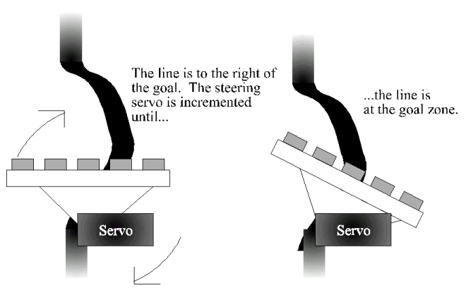
To follow the line, five infrared reflectance sensors are used. The sensors are mounted on the servo steering wheel. The idea is that if the steering wheel can align with the line, the rest of the robot can easily follow.

Software Design
The robot begins with a calibration of white and black values. The sensor values from all 5 sensors are averaged together, to create one dark value and one light value for all the sensors. The average of the light and dark value creates a threshold right in the middle between light and dark.
The main program runs in a continuous loop. At the top of the loop is a "for" loop to read the values of the reflectance sensors. Each sensor is compared with the threshold values, and values of 0 (light) or 1 (dark) are assigned to elements of an array. This array is used to determine the location of the line, which is the one element that is dark (1).
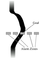
The arrangement of the reflective sensors creates a goal zone in the center and four alarm zones surrounding it:

If the line falls on an alarm zone to the left of the goal, the program will begin to increment the servo to the left. If the line is to the right, the servo will begin to increment to the right. The increment for an outer alarm zone is greater than the increment for an inner alarm zone, since the course of the robot is more astray from the line, and must be corrected faster. Once the line is back on the goal, the incrementing will stop.

Our method allows for a smooth following of the line. When the robot is following an arc, the servo will turn until the line is on the goal. This allows the robot to follow large parts of an arc with little or no correction.
Time Trials
Once the software design was finalized, the robot was run three times for five different motor power levels. Here are the results:
Motor Time (sec)
Power % 1 2 3 Average
60 8.46 8.90 stall 8.68
70 4.79 4.61 4.20 4.53
80 4.01 4.02 4.07 4.03
90 lost 4.00 4.08 4.04
100 3.50 3.39 lost 3.45
Best Time: 3.39 seconds
Average Time (overall): 4.84 seconds
Adjustments:
The rate at which the servo is incremented must be altered when traveling at speeds greater than 80%:
Speed: Servo Increment:
60% to 80%: +/- 40 for inner alarm zones, +/- 90 for outer alarm zones
90% to 100%: +/- 60 for inner alarm zones, +/- 110 for outer alarm zones
These values were found by trial and error. If the robot has difficulty in following a curve, the increment values are simply raised until the robot behaves.
Timeline of Main Events:
5/14/2001: Brainstorming and strategy.
5/17/2001: Robot constructed. Initial software design began.
5/24/2001: Software design finished and tested.
5/31/2001: Final testing and data collection.
Return to Challenge Page